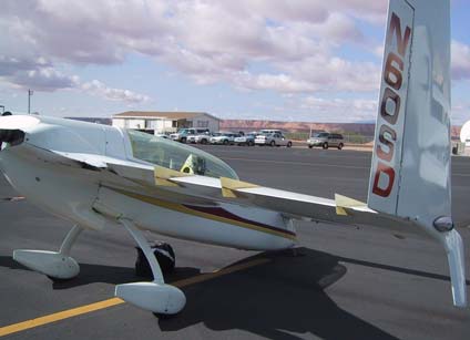
Flow fences
shown here on Shirl Dickey's vintage Vari Eze.
Aerodynamic Flow Fence
Technicalities
Span wise flow characteristics of swept wings are well understood
and often treated with flow correcting devices. Most commonly they
are installed on top of the wing and rarely behind or below.
Airliners do not have them since they have fully articulating trailing
edges.
The following text only applies to the Vari
Eze wing directly and other swept
wings
indirectly.
While span wise flow still exists on trailing edges of unswept wings, it is
so
small that restricting flow fences would probably not have a significant
benefit.
On swept wings flow fences should not be installed on aileron control
surfaces
since this loads them up to the point that roll authority is all
but
lost.
In an effort to reduce approach and landing speeds of Light Speed
Engineering's
Vari Eze, span wise flow fences were installed on the trailing
edge
and flight tested.
The overall change in low speed performance was remarkable. It was
immediately
noticed that take- off distance is reduced 10-15% climb rate is
improved
20% and most noticeably approaches can be flown at least 10-15%
slower
resulting in a significantly shorter landing distance, nearly 30%
less.
There was no measurable decrease in top speed. The configuration of
the
airplane tested had the standard 3 Vortilons on each wing leading edge
with
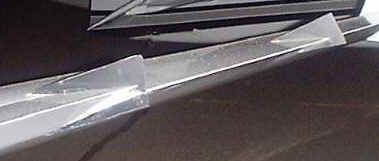
three roughly equally spaced flow fences between the outboard end of
the
aileron and the winglet. The shape of each fence does not appear to be
critical
but it is believed that it is important that they exist on top of,
behind
and below the wing surface to completely isolate the section outboard
of
the fence from any span wise flow that is developed inboard of it. Span
wise
flow on swept wings at high angle of attack around the trailing edge
redevelop
in a short span thus several fences are more beneficial.
Technically speaking the slope of the CL/alpha curve of the main wing is
increased
especially in the +5 to +14 deg AoA region. Max AoA at equal
flight
conditions was reduced by 2.2 deg. from 16.2 down to 14 deg. Vmin is
not
noticeably reduced since it is elevator limited. Due to the higher main
wing
C/L generated at max AoA the elevator is more loaded even though max
alpha
is reduced. The increased pitching moment loads the elevator to stall
at
a lower deck angle.
The only negative observation is a reduced roll response at the lower
speeds,
probably due to lower dynamic pressure.
Special thanks to all the customers of Light Speed Engineering who have made
this
and other research possible.
Klaus Savier
Light Speed Engineering, LLC
|
 ™
™