THE LIGHT SPEED ENGINEERING™
PLASMA
II, II+, and III CDI
SYSTEMS
INSTALLATION AND OPERATION MANUAL
FOR FOUR AND SIX CYLINDER INSTALLATIONS
LIGHT SPEED ENGINEERING,
LLC
416 EAST SANTA MARIA STREET, HANGAR #15
PO BOX 549 SANTA PAULA, CA 93060.
phone: (805) 933-3299 fax: (805)525-0199
E-mail:
lightspeedengineering.com
COPYRIGHT LIGHT SPEED ENGINEERING,
LLC 2006, VERSION
022209
CONGRATULATIONS ON YOUR PURCHASE OF A LIGHT SPEED
ENGINEERING (LSE) PLASMA CAPACITOR DISCHARGE IGNITION (CDI) SYSTEM.
YOU WILL NOW BE ABLE TO EXPERIENCE THE SIGNIFICANT
ADVANTAGES OF DISTRIBUTORLESS HIGH ENERGY ELECTRONIC IGNITION IN FLIGHT PERFORMANCE AND EFFICIENCY.
TO ENSURE RELIABLE LONG TERM OPERATION, AND TO ACHIEVE
THE FULL PERFORMANCE POTENTIAL, PLEASE READ THE ENTIRE MANUAL CAREFULLY, AND FOLLOW THE PROCEDURES.
SINCERELY,
KLAUS SAVIER,
President LSE
NOTICE
Light
Speed Engineering Plasma CD Ignition products are
intended only for installation and use on aircraft which are
licensed by the FAA in the “experimental” category
pursuant to a Special Airworthiness Certificate, or aircraft
which are the subject of a Supplemental Type Certificate for
modifications which include Plasma ignition.
All products must be installed and used in accordance
with the current instructions from Light Speed Engineering which
are available on the website at www.LightSpeedEngineering.com. |
WARNING!
Failure
of the Plasma CD ignition system(s) or products, or improper
installation of Plasma ignition systems or products, may create
a risk of property damage, severe personal injury or death.
Though
a system manual may be shipped with your order, the MOST CURRENT
AND COMPLETE version of the INSTALLATION INSTRUCTIONS AND
OPERATING MANUAL for each of our products is available on our
website under “Manuals”, or by calling Light Speed
Engineering at 805-933-3299.
ALL
SYSTEMS AND PRODUCTS MUST BE INSTALLED ACCORDING TO THE
INSTALLMENT INSTRUCTIONS CONTAINED IN THE OPERATING MANUAL
POSTED ON OUR WEBSITE. |
TABLE OF CONTENTS
1.1
Features and Options
1.2
Hall Effect Module
1.3
Direct Crank Sensor
2.1
Hall Effect Sensor
Module Installation
2.2
Flywheel
2.3
Direct Crank Sensor
Installation
A. Overview and Lycoming Engines
B. Continental 550 and Franklin Engines
C.
Continental O-200 Engines
2.4
Plasma CD Ignition Module Placement
2.5
Ignition Coil Installation
2.6
Spark Plug Adaptors and Spark Plugs
2.7
Electrical Requirements & Operation
2.8
Electrical Connections
A. Power Supply
B. Primary
Ignition Wire
C. High
Tension Leads
D. Manifold
Pressure Line
2.9
Important Installation Requirements
3.1
Phasing (cylinder firing order)
3.2
A. Timing Requirements for Your Engine
B. Timing the Ignition System- Procedure
3.3 Run Up Tests
3.4 In-flight Tests
4.1 Starting Problems
4.2 Radio Noise
LIST OF FIGURES
FIGURE
1.
DUAL POWER SUPPLY
FIGURE 2. Plasma II,
II Plus & III Input Connector Diagram (PDF
File, Please allow longer loading time)
FIGURE
3. Plasma II Plus
& III Output Connector Diagram
(Please allow longer loading time)
FIGURE
4.
DUAL IGNITION INDICATOR LIGHTS
Section 1
INTRODUCTION
This manual covers all 4 and 6 cylinder versions of the LSE PLASMA
II, II+, and III CDI Systems. Included herein is a description of concept and design philosophy, installation instructions,
testing procedures, troubleshooting guidelines, and repair and warranty instructions for those systems.
The LSE PLASMA CDI System was designed to replace one or
two magnetos on home built aircraft and in other aircraft for which a specific supplemental type certificate has been
issued.
1.1 FEATURES AND OPTIONS
The PLASMA CDI ignition systems can replace an impulse or non-impulse magneto
since its automatic spark retard to top dead center ensures reliable starting under all
conditions.
LSE PLASMA CDI Systems provide optimum ignition timing for best
performance under all conditions. The extremely wide timing curve extends from 15° to 42° degrees BTDC.
Full retard
for starting holds the timing back to TDC. After starting, the system advances according to RPM and manifold pressure.
For the ultimate improvement in performance and ignition reliability
you can replace both magnetos with LSE Plasma CDI Systems. In this case LSE recommends the installation of a standby
battery as a backup to your electrical system
(see Figure 1) and dual ignition indicator lights (see Figure 4). Due to the lightweight of the LSE PLASMA CDI Systems, a dual system with
backup battery is still several pounds lighter than two magnetos. If two systems are used, either or both tachometer
outputs can be used.
Dual systems can be connected to each other such that each system
knows if the other one is operating. If one of the two systems is turned off or has failed, the remaining system will
automatically shift its timing curve to provide optimum engine performance with one system.
This eliminates the common power loss when one magneto is turned off. The extremely wide operating
voltage range, from 5v-35v allows hand starting long after the electric starter has stopped due to a low battery.
On aircraft with 24v systems no special considerations need to be
addressed, just hook up the power leads to positive (+) and negative or ground (-) as you would with a 12v electrical
system. There is no need to install an external noise filter capacitor on LSE PLASMA CDI Systems; they were designed
from the ground up to operate in aircraft with radios.
The LSE PLASMA CDI System can be turned
off and on at any time in
flight without the risk of misfiring.
The systems can be turned on by supplying power to
the power lead
on the input connector via a
toggle switch.
PLASMA II PLUS and
PLASMA III systems,
additionally, have a "P lead" from the output connector that may be used with an aircraft key
switch.
An optional digital timing display can be installed to monitor the
current ignition advance (PLASMA II PLUS and PLASMA III systems only). This output can also be used to supply a data acquisition system with timing information.
On all Plasma systems the 15 pin "D-sub" input connector to the system is
pre-wired with its power
and signal inputs. A pulse tach output is also provided on this connector. Refer to
the Input Connector Diagram.
RG-400 leads are supplied as primary
ignition wires with BNC connectors,
ready to connect to the single electronic module. They must be terminated at the LSE provided ignition coils with
standard spade connectors.
LSE PLASMA CDI Systems are designed using discrete logic in place of
programmable memory or micro processors, to avoid any potential problems from static discharges, minor lightning strikes
or single event upsets (SEU).
As with all electronic devices, their enemies are heat, moisture and
vibration. This should be considered for the best installation of the system.
1.2 HALL EFFECT MODULE
4-cyl. LYCOMING TYPE ONLY
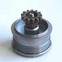 The
Hall Effect sensor module (shown at left) is used in place of a magneto and is designed to make the installation
extremely easy and more similar to magnetos. Two modules can be used to provide full trigger redundancy when two
electronic ignitions are used.
The
Hall Effect sensor module (shown at left) is used in place of a magneto and is designed to make the installation
extremely easy and more similar to magnetos. Two modules can be used to provide full trigger redundancy when two
electronic ignitions are used.
A standard magneto gear from a non impulse magneto must be provided. A
timing light is built into the module. The 9 pin "D-sub" connector on the sensor module simply connects to the
harness from the ignition module.
The
Hall Effect sensor module should be removed every 50 hours and inspected for
gear, bearing, and seal wear. After first inspection, inspect as necessary
or at least every 100 hours by removing cover plate and checking for bearing and
seal wear.
1.3 DIRECT CRANK SENSOR
Alternatively, the direct crank
sensor system provides complete redundancy for single or dual PLASMA CDI
systems. This crank sensor concept requires removal of the flywheel for
installation. Its reliability and performance is expected to be superior
to that of the accessory case mounted Hall Sensor Module because of its lack of
bearings, seals, and gears. All 6-cylinder versions use direct crank
sensors.
The LSE PLASMA CDI Systems contain the following
items. Items listed are for single systems; if dual systems are ordered,
quantities of most parts double. If any items are missing or damaged, contact LSE immediately.
|
HALL
EFFECT MODULE
|
CRANK
SENSOR
|
CRANK
SENSOR
|
| 4-cylinder system
PLASMA
Installation Instr.
1 PLASMA Ignition Module
1 Hall Effect
Sensor Module
1 Hall Effect
Sensor Module gasket
Wiring Harness
2 dual output ignition coils
with mounting bracket
2 RG400 primary
cables and 4 spade terminals
4 High Tension Ignition Leads
4ea. Spark Plugs
and Inserts
|
4-cylinder system
PLASMA
Installation Instr.
1 PLASMA Ignition
Module
Crank Sensor
circuit board and bracket
1 Mag hole cover
2 Trigger Magnets
per Ignition System
Wiring Harness
2 dual output
ignition coils with mounting bracket
2 RG400 primary
cables and 4 spade terminals
4 High Tension Ignition Leads
4ea. Spark Plugs
and Inserts
|
6-cylinder
system
PLASMA
Installation Instr.
1 PLASMA Ignition Module
Crank Sensor
circuit board and bracket
1 Mag hole cover
2 Trigger Magnets
per Ignition System
Wiring Harness
3 dual output ignition coils
with mounting bracket
3 RG400 primary
cables and 6 spade terminals
6 High Tension Ignition Leads
6ea. Spark Plugs
and Inserts
|
Section
2 INSTALLATION
CAUTION!
BE CAREFUL NOT TO DRILL INTO ANY PRIMARY AIRCRAFT STRUCTURE
WHILE MOUNTING YOUR PLASMA CDI SYSTEM(s). THE BEST IGNITION SYSTEM IN
THE WORLD WILL BE NO HELP IF YOUR MAIN SPAR FAILS.
It is important to locate antennas, receiving or transmitting,
away from the engine and ignition systems.
SHIELDING:
The wires
supplied in the PLASMA CDI System kit are high quality ignition leads designed to transmit spark energy
efficiently and to suppress ignition noise. Therefore, they usually do not need shielding.
It is also
necessary to
use resistor spark plugs to avoid radio noise. High tension leads should be kept as short as possible.
ADF and Strikefinder use may call for additional shielding.
2.1 HALL EFFECT SENSOR
MODULE INSTALLATION
To
install the accessory case driven Hall Effect Sensor Module, please follow these
instructions:
Install
a magneto drive gear from a non-impulse magneto onto the shaft of the
sensor module using the same woodruff key as well as the LSE supplied washer and
locknut.
Fasten
the gear in a soft jaw vise and tighten the nut to 30 lbs/ft ensuring that the
washer is centered on the shaft.
The
module can be installed on either mag pad using standard clamps. Install
all system wiring except the BNC connectors (primary ignition wires) on the
ignition module.
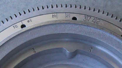
Remove
one sparkplug from each cylinder and turn the crankshaft to TDC #1 using the
factory timing marks on the engine side of the flywheel.
Turn
electrical power on and rotate the sensor module in the accessory case counter-clockwise
until the green light on the module case turns on and then off again.
Maintaining its position, fasten the sensor module with the toe clamps commonly
used with Slick Magnetos.
This procedure positions the Hall Effect Module for engines normally timed at 25
degrees BTDC (usually standard compression ratio).
If
your engine is normally timed at 20 degrees BTDC (usually compression ratios of
8.7:1 or higher), the timing must be retarded 5 degrees. In this case,
position the crankshaft to 5 degrees past TDC in the direction of rotation and
use the procedure outlined above.
To
ensure the timing is set correctly, LSE recommends that you check the timing
using an automotive strobe light. Please
refer to section 3.2: “Timing Light Hookup and Tests” for
details.
The
Hall Effect Sensor module should be removed after 50 hours and inspected for
gear, bearing, and seal wear. After first inspection, inspect as necessary
or at least every 100 hours by removing the cover plate and checking for bearing
and seal wear.
2.2 FLYWHEEL
To
verify proper operation of the ignition system, the timing must be checked with
a timing light (strobe light) as described in section 3.2. For this, the
flywheel or prop-extension must be graduated with the proper timing marks. Also
an indicator should be built to mount on the case center adjacent to the timing
marks on the flywheel. Always use
only the timing marks on the engine side of the flywheel.
NOTE:
You may also send the flywheel to LSE for trigger magnet and timing mark
installation. The cost is $75 plus $15-25 for insured shipping.
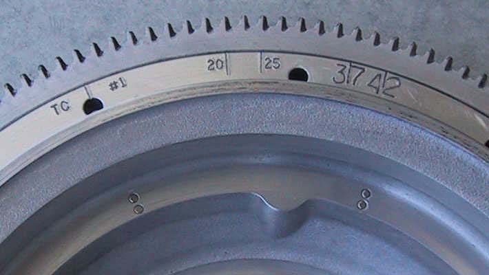
LYCOMING
ENGINES
TDC,
20 deg., and 25 deg. BTDC markings are stamped on the flywheel engine side by
the factory. Add markings at 35, 40
and 45 degrees. These markings
should be duplicated 180 degrees out, to reference the other ignition coil
timing. On 6 cylinder engines the
factory timing marks should be duplicated twice, 120 deg. and 240 degrees from
TDC.
If
you are installing a direct crank sensor system, refer to section 2.3 for the
installation of the trigger magnets on the flywheel.
A large diameter alternator pulley is required (8.5” ID).
ALL
OTHER ENGINES
Apply
the same concept to install timing reference marks on the propeller extension or
spinner bulkhead.
2.3 DIRECT CRANK SENSOR
INSTALLATION
A. Concept Overview for all
Engines
Lycoming-type Specific Installation Instructions
The
crank sensor circuit board has two completely independent triggering systems if
it is used for dual Plasma CDI applications. On single installations, only the outer set of sensors and associated
wiring is installed.
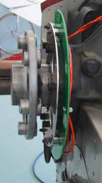
Remove the flywheel to install the magnets and crank sensor
assembly. The outer trigger magnets are installed in the flywheel on a 4.000"
radius.
The inner trigger magnets, used for a second system, are installed on a
3.840" radius (refer to the picture below). You may wish to send your
flywheel to LSE for installation of the magnets and the timing marks; cost is
$50 plus shipping; plan on 1 day plus shipping time.
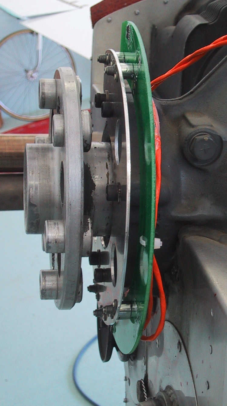
Please
refer to the attached pictures and those on the Crank Sensor page of the web
site (www.LightSpeedEngineering.com)
to mount the sensor plate to your crankcase and integrate the trigger magnets
into your flywheel. Use a number 32 drill, 1/8” deep so that the magnets can
be pressed in flush with the surface. Use Loctite and stake around them.
Two or
four magnets are included. Single systems require only two magnets on the 4” radius. Looking into the pulley side of the
flywheel, the left magnet position should always line up with the TDC indication
under the starter ring gear. For the other magnet position, add 20 degrees to
the recommended timing for your engine and install it on the same radius to the
right of the first magnet. On engines that should have their
magnetos timed at 25 degrees, the leading magnet should be installed at 45 deg BTDC
and thereby 45 degrees to the right of the TDC magnet. High compression
engines should have their leading magnets installed 40 degrees BTDC. Only the
magnet's south pole can
trigger the sensors. This is the
face marked with an X and therefore, should point to the sensor.
In other words, the X must be visible after installation.
If the X is not clearly visible, use a compass to identify the correct polarity.
Large diameter alternator pulley required (8.5" ID).
If
you have seal retainer plates installed, remove them and use existing holes to
mount the bracket. You might have to
adjust the holes in the bracket using a dremmel to make them align with the
existing holes. If the bosses are not drilled, use
the mounting plate as a drill template as follows.
Align plate concentric to crankshaft by registering on
centering tabs. Visually align the
crankcase split line with the v notches between the top and bottom 2 holes of
the mounting plate. Mark the
crankcase mounting locations through the existing holes in the bracket.
If possible, use a #2 centering drill for a pilot hole.
Drill #6 (0.2040) x 5/8” deep. Tap
Ľ-20. For best results, use a
2-flute spiral point HSS tap with aluminum tapping fluid such as Tap-Magic.
Once the bracket is mounted to the crankcase, remove the three
alignment tabs then remove the two control tabs.
This sequence allows you to later verify that the alignment tabs were
removed. If the circuit board was
removed for this operation, re-install it.
All screws holding the crank sensor circuit board to the mounting bracket
must be secured with Loctite and the proper torque.
The 0 degree mark on the circuit board should now align with the split
line in the crankcase when the screws are fastened in the center of their
positioning slot.
Now
that the sensor plate is installed, perform a simple operational check:
Disconnect all high-tension leads from the ignition coils. With power to
the system and all else connected, take any magnet and swipe it back and forth
past each sensor (speed is important, > 2x per second).
Every other pass should produce a loud spark at the coil. Only the south pole works. Check each sensor.
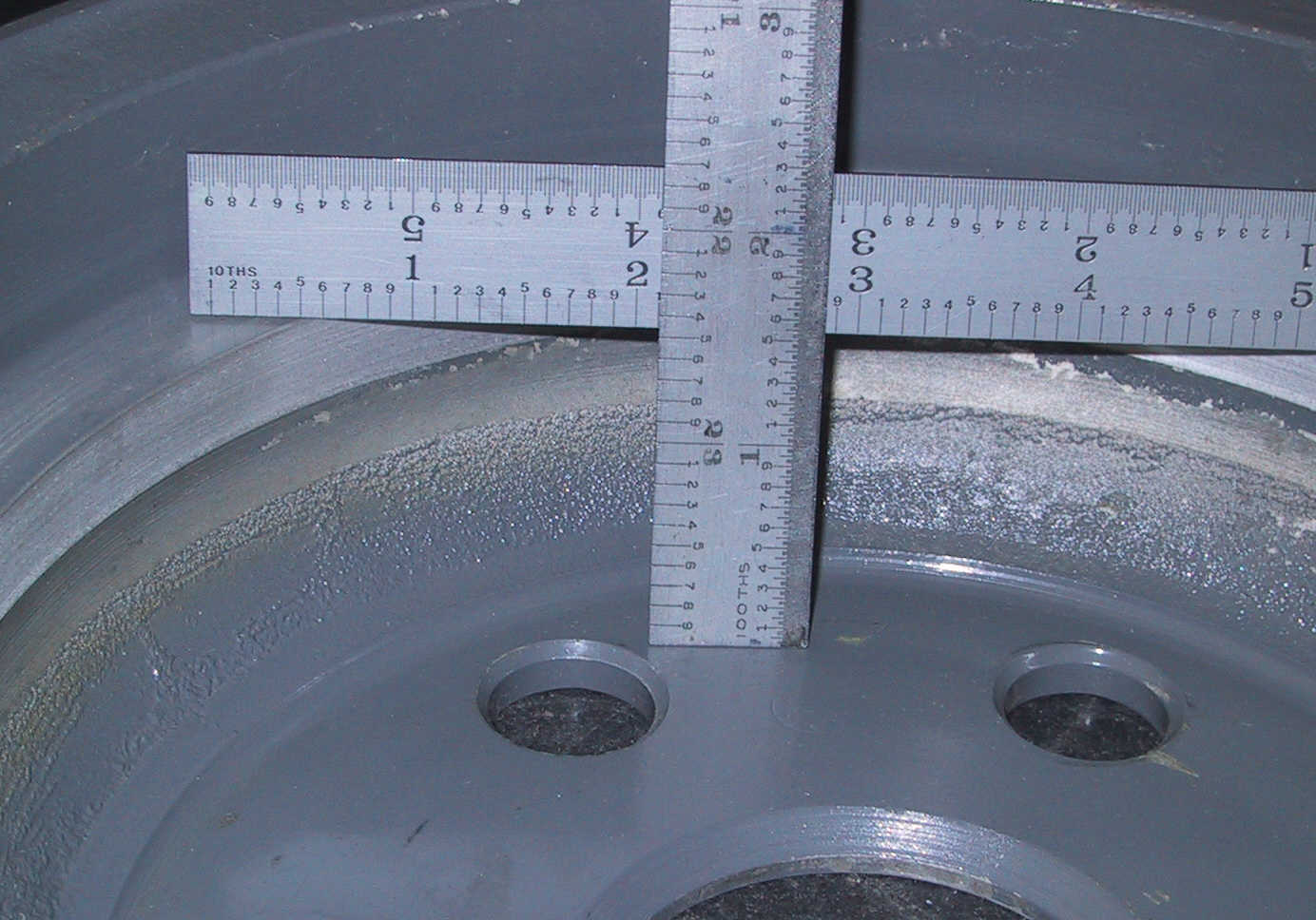
Lycoming external engine dimensions can vary significantly, so you need to
verify the proper clearance between the sensor and the magnets installed in the
flywheel surface. Two measurements need to be compared to determine the gap.
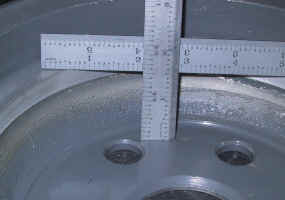
·
First, measure the height from the inside of the flywheel where it
touches the crankshaft flange to the surface that has the magnets installed.
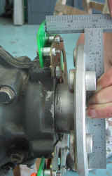
·
Then measure from the face of the crankshaft flange back to the
sensor face on the circuit board. This second dimension needs to be larger by
.030”- .060”. The clearance should fall within these parameters with
the crankshaft pushed in and pulled out.
Too little gap and a flexing crankshaft
might touch the sensors.
Too much gap will not activate them.
Adjust
by adding washers to the circuit board spacers (adding clearance) or by adding
washers underneath the bracket attachments (subtracting clearance).
**Note- Magneto removal:
When removing the magneto(s), be sure to remove the
mag with its drive gear and pilot bearing. Install the mag hole cover
plate provided by LSE, in place of the magneto. Use only liquid sealant and the magneto "toe
clamps" to secure
this plate. Gaskets are not
recommended as they may distort the cover plate.
You may wish to send your
flywheel to LSE for installation of the magnets and the timing marks; cost is
$75 plus shipping; plan on 1 day plus shipping time.
2.3 DIRECT CRANK SENSOR INSTALLATION
B. Continental 550 & Franklin Engines
The following instructions are written for 6-cyl. Continental Engines, but
4-cylinder Continentals follow a similar procedure and may use this as a guide.
Additional instructions for 4-cyl. Continental Engines
can be found in the next section, 2.3-C.
The
mounting bracket supplied by Light Speed Engineering is common for both the
large 6-cylinder Continental and the Franklin engines.
Two sets of mounting holes are provided using the same pattern as the
crankshaft main seal retainer plates.
The mounting bracket bolts directly to the front of the crankcase in
place of the seal retainer and also acts as a seal retainer.
Two
sets of centering tabs are part of the bracket and are to center the bracket on
the two different crankshaft diameters.
If you are using a Continental engine, remove the larger three tabs.
It may be necessary to modify the mounting holes slightly to be able to
bolt the bracket to the crankcase while all three alignment tabs are touching
the crankshaft.
After
the bracket is secured, remove all centering tabs then remove the control tab.
This allows for easy verification later that the alignment tabs have been
removed and are not rubbing on the crankshaft.
Now
the circuit board can be installed with its 6 mounting screws and spacers.
Apply blue Loctite and 12"/lb or torque. Visually align the 0 degree arrow on the circuit board with the crankcase
split line.
The
magnet holder is mounted under two of the prop fasteners such that the second
magnet set (in the direction of rotation) aligns with TDC crankshaft position.
When the crankshaft is in the TDC position for cylinders 1 & 2, this
second set of magnets is then directly opposite the top Hall effect sensors
(labeled 0 degrees) on the circuit board.
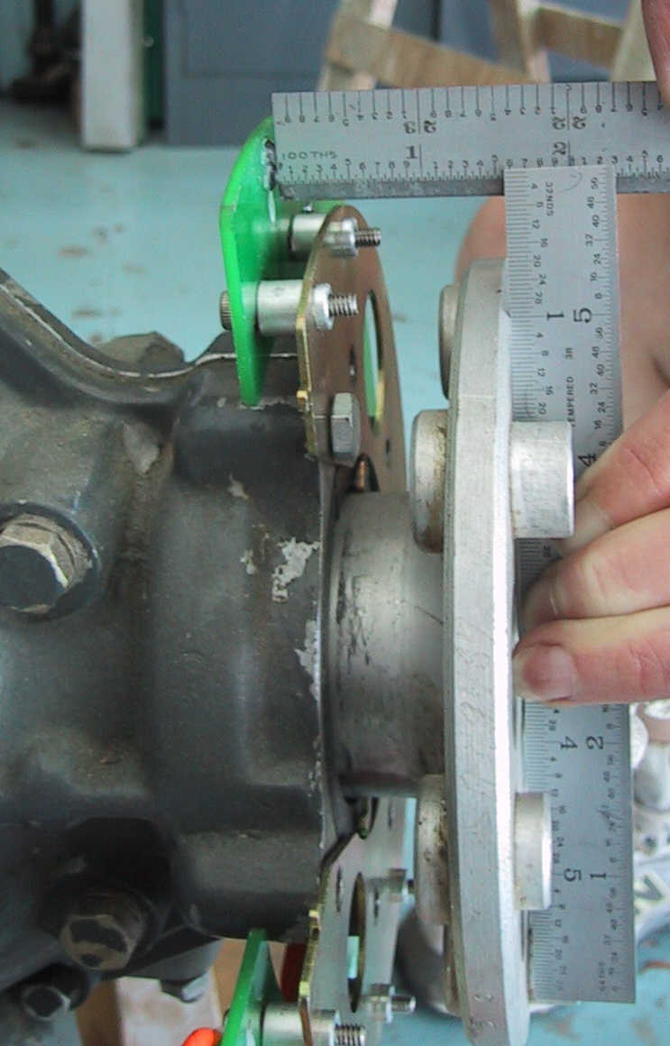
The gap between the sensor surface and magnet holder surface must be
0.030” – 0.060”.
Shim the circuit board with number 8 washers to achieve this clearance
when the crankshaft is full forward and all the way back.
Remember to check that the gap does not exceed 0.060” between the
magnet holder surface and the hall effect sensors at each sensor location.
The
steel counter weight is mounted directly opposite the magnet holder using the
same technique.
See the Continental Direct Crank Sensor installation picture for
reference.
Torque
the prop bolts to factory spec.
Continental
Engine Magneto Removal Notes:
On
the 6-cylinder Continental engines, each magneto shares a common gear with the
opposing vacuum pump / standby alternator drive.
Single
Mag / Single Plasma Use:
If one magneto is retained for use with a Plasma CDI, the vacuum pump pad
opposed to this magneto can be used for a pump or alternator.
Subsequently, the other drive should be disabled by removing the magneto
and associated gear assembly. Seal
both the vacant vacuum pump pad and magneto pad using cover plates.
Dual
Plasma Use:
If two Plasma CDI systems are used, both magnetos and their drive gear
assemblies are removed. This disables the vacuum pump pads. If it is necessary to drive a vacuum pump, a magneto and the
drive gear assembly can be used to enable this drive. The points should be removed to disable the magneto.
Other parts, such as the ignition coil, can be removed from the mag to
save weight and drag.
Alternatively,
a starter drive with a pulley for air conditioning is available from
Continental. This pulley can also
be used to drive a rear alternator.
* Important!
Over-voltage protection must be provided with any electrical system.
2.3 DIRECT CRANK SENSOR INSTALLATION
C. Continental O-200 Engines
Step
1:
The Continental O-200 has 4 mounting bosses on the front of the engine.
If they are drilled, the mounting holes in the LSE supplied 0-200 bracket
should match the bolt pattern on the engine.
(If your crankcase is drilled, go to step 5.
Otherwise, proceed to step 2.)
Step
2:
The dimensions for the factory hole pattern are shown in the Continental
engine overhaul manual. If the case is not drilled, it is not possible to get to the
factory locations without removing the crankshaft (which is not an option).
New holes have to be drilled slightly inboard of the factory locations.
The
case has some “draft” in the casting so the forward face of the bosses in
question first need to be filed flat and parallel to the flange.
This takes about an hour of filing if you have sharp files. Protect the main seal from the shavings by masking.
Start with a Vixen file and measure frequently using the mounting bracket
as a flat reference.
Step
3:
Press out one of the drive-lugs from the flange by using a socket and a
bolt. If it is hard to get out, a
little heat might help. Don’t use a hammer!
Step
4:
Once the drive-lug is out, you have enough access to reach the bosses on
the case for drilling and tapping. Hold
the mounting bracket concentric to the crankshaft to drill through the bracket
and into one of the bosses.
Use
a number 6 drill, ľ deep. Tap this
first hole using a Ľ-20 tap and hold up the steel bracket as concentric as
possible. Adjust the hole as necessary when you enlarge it for the Ľ”
bolt size. Bolt the bracket down to
hold it in place while you drill the other three No. 6 holes. Remove the bracket and tap all.
Now open up the holes in the bracket to accept all 4 bolts holding the
bracket parallel and concentric to the crankshaft flange.
Step
5:
On final installation of the mounting bracket, use blue Loctite and/or
safety wire to secure the bolts. Install
the bracket per picture #1 (following page), with the slots lining up with the split line of the
case and as concentric to the crankshaft as possible.
Step
6:
Now the circuit board can be installed with it’s 6 mounting screws and
0.87” spacers. Use blue Loctite and
12"/lb of torque. Visually align the
0 degree arrow on the circuit board with the crankcase split line. (Picture 2, following
page)
Step
7:
Next, the magnet plate is mounted such that the second magnet set (in the
direction of rotation) aligns with TDC crankshaft position and the magnets face
the engine. Then the crankshaft is
in the TDC position for cylinders 1 & 2, this second set of magnets is then
directly opposite the top Hall effect sensors (labeled 0 degrees) on the circuit
board. (Picture 3, following
page)
Install
the trigger magnet plate between the propeller extension and the propeller
flange. Confirm the magnets are pointing towards the engine.
Step
8:
Measure the gap between the magnet plate and the copper face of the
direct crank sensor board. Make adjustments by uniformly shimming all 6 spacers.
If the spacers are too long, use a lathe to shorten all of them by and
even amount. Do not make any custom
spacers or the board will warp when tightened down.
Contact Light Speed Engineering if you need help with this.
If
you are using 1/8” diameter magnets, the gap should be between 0.030” and
0.060” with the crankshaft pushed in and pulled out.
There usually is about a 0.010” endplay.
If you have Ľ” diameter magnets, the gap can be as much as 0.1”
.
When
installing your propeller extension, be sure you have at least 6 threads of your
bolts engaging with the drive lugs.
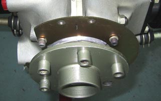 |
Picture
1:
Crank
Sensor
Mounting
Bracket
Installed
|
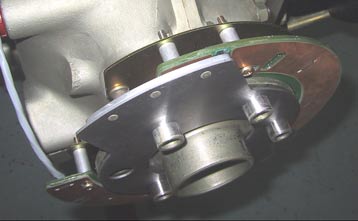
 |
Picture 2:
Direct Crank
Sensor
Board
Attached to
Crankcase
Mounting
Bracket |
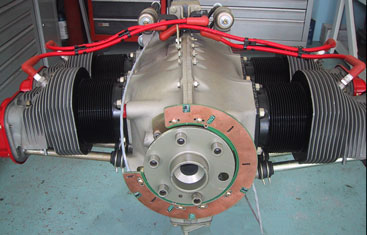
 |
Picture
3:
Crank
Sensor
Board and
Trigger
Magnet
Bracket
Installed.
|
2.4 PLASMA CD
IGNITION MODULE PLACEMENT
The
PLASMA CDI module should be mounted in a clean and dry place on
the cold side of the firewall.
If space limitations require mounting on the engine side of the firewall,
a protective metal cover should be used to protect the module from water/engine
cleaning materials and heat.
Air must be allowed to flow between the bottom of the
module and the mounting surface.
On
6-cylinder
systems, cooling air must be supplied to the box
via the port on the 15-pin connector side of the ignition module.
For 6-cyl systems that do not have a cooling port, contact LSE for this
modification.
Cooling is not required on 4-cyl systems.
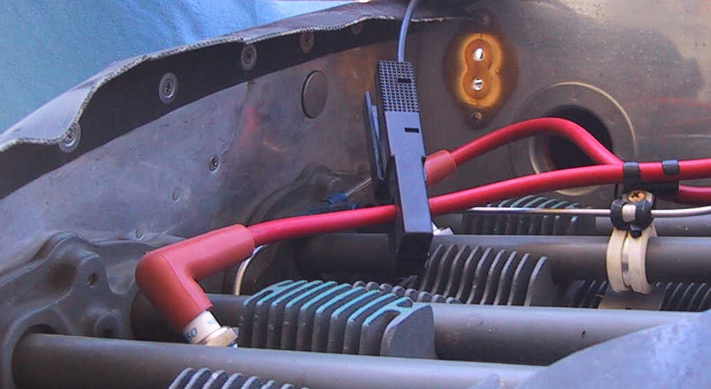
2.5 IGNITION
COIL INSTALLATION
Ignition coils are typically mounted on the top center of the
engine. They can also be mounted on the motor mount tubes using adell
clamps or on the firewall to a piece of angle aluminum. Ignition coils
should be mounted so that spark plug lead length will be kept to a minimum for
maximum spark energy and minimum noise. It is important that each coil
connects to opposing cylinders, i.e. one coil fires cylinders 1 and 2 and
the other coil fires 3 and 4.
2.6 SPARK PLUG ADAPTORS AND SPARK PLUGS
·
Aircraft engines using 18mm & ˝”
reach spark plugs use adaptors with the same outside thread and a 14mm &
ľ” reach inside thread.
Use LSE high performance HP plugs, Denso
spark plugs starting with a W or NGK spark plugs starting with a B in their
designation.
·
Aircraft engines using 18mm & ľ”
reach spark plugs use one of the following:
o
LSE long reach adaptors with 12mm inside
thread for Denso X27GPR-U or X24GPR-U or
equivalent 12mm spark plugs.
OR
o
Optionally, for high performance applications,
use LSE HP-LR (long reach) adaptors with 14mm inside thread for high performance
HP-LR 14mm spark plugs.
*
WARNING- DO NOT USE SHORT REACH ADAPTERS IN ENGINES THAT USE LONG REACH AIRCRAFT
PLUGS OR VICE VERSA.
Engines
normally timed at 25 degrees BTDC:
These are normally engines with compression ratios less than 8.7:1. Gap spark
plugs fired by the CDI to .032"-.040".
Engines
normally timed at 20 degrees BTDC:
These are usually engines with compression ratios of 8.7:1 or higher. Gap spark
plugs fired by the CDI to .026"-.035".
Turbo / Supercharged engines should gap the spark plugs to .026” - .035”
while turbo normalized engines should gap the spark plugs according to the
compression ratio.
WARNING!
- WIRING
CAN CAUSE ELECTRICAL SHOCKS WHEN IGNITION IS TURNED ON.
- DO NOT
TOUCH ANY WIRES WHEN SYSTEM IS IN OPERATION.
-
DISCONNECT BATTERY
DURING INSTALLATION TO AVOID SHOCK.
2.7 ELECTRICAL REQUIREMENTS AND OPERATION
Electrical System Requirements
All
Plasma CDI systems can be used with 12 or 24 volt electrical systems.
Input voltages above 35 volts or reversed polarity will cause system
damage.
For
this reason it is mandatory that all aircraft using Plasma CD Ignitions are
equipped with over-voltage protection in their alternator charging system(s).
Over-voltage is a requirement for certified aircraft.
Power connection must be directly to the battery terminals to avoid
voltage spikes and electrical noise. Aluminum
should never be used as an electrical conductor for the Plasma CDI.
Use only the supplied aircraft quality stranded wire.
Minimum
supply voltage for starting is 6.5 Volts.
Minimum
operating voltage is 5.5 Volts.
Electrical Operating Instructions
No
operational limits or special procedures are necessary during normal use.
You can either hand start your engine or use your electrical starter.
All Plasma CDI systems retard timing to TDC during start and advance
timing optimally for all flight conditions based on manifold pressure and rpm.
-
In
case of a charging system failure, it is recommended that you land at the
nearest safe airport and repair the charging system before further flight.
-
If
you are using Dual Plasma CD Ignition, you can turn one system off, together
with all other electrical loads not essential for flight, to maximize your
range with your remaining battery capacity.
-
Dual
Systems only: If you have installed an aux battery per the LSE supplied
drawing, monitor your voltmeter and do not switch to the aux battery until
the supply voltage of the main battery is below 6.5 Volts or the engine is
not running smoothly. After switching to the aux battery, your voltmeter will read
the voltage remaining in your aux battery.
-
Do
not switch your main alternator breaker in flight to avoid potentially
damaging voltage spikes. This does not apply to the alternator field breaker.
**
The above electrical operating information should be contained in the
Aircraft Operating Manual. **
2.8 ELECTRICAL CONNECTIONS
HERE
ARE SOME NOTES ON HOW THE SYSTEM IS WIRED UP:
The
PLASMA
CDI
System
includes a pre-assembled electrical harness/connector(s) with all essential
wires ready to route between the triggering mechanism (Hall Effect Sensor,
Direct Crank Sensor, or Trigger coils) and Plasma CD ignition module input
connector. The input connector, output connector and manifold pressure
input barb are located on one side of the Plasma CD module; BNC connectors for
the primary ignition wires are located on the other side of the Plasma CD
module.
POWER WIRE CONNECTION
*Note continuation of shield - insulated.
A. Power Supply -
·
When connecting the power supply, route the positive
lead to a pull-able breaker, 4-cyl
systems use 5A and 6-cyl systems use 7.5A,
and then directly to the battery plus terminal, bypassing any electrical buss or
master solenoid. Refer to the Input Connector Diagram & the
Electrical Requirements section 2.7.
·
The positive 12 or 24 Volt power supply
(center conductor) is soldered to pins 7 and 8 of the input connector (at
LSE) and is connected to the breaker (and toggle switch if used) per the Power
Wire Connection picture, above. Continue
this wire directly to the battery terminals.
·
The shield is used as a ground return
(negative supply) and is continued across the breaker (and toggle switch if
used) per the Power Wire Connection picture (above), then connected to
the battery negative terminal.
·
Power connection must be directly to the
battery terminals to achieve the best reliability, to avoid voltage spikes, and
to minimize radio noise.
·
If a standard aircraft key switch is used
as an on/off switch, see Note 4 on the Input Connector Diagram. Do
not connect power from the Plasma CDI to the key switch. An aircraft key switch can
only be used with some Plasma I systems and all of the Plasma II Plus and Plasma III systems.
·
On systems shipped before September 2005,
two individual shielded wires were used for positive and negative supply.
In this case, the shield is not connected at the battery end.
WIRING
THE IGNITION SYSTEM
An ohmmeter may prove helpful in verifying your connections.
 B. PRIMARY IGNITION WIRE
Route the primary ignition wires (RG400 coax) to the ignition coils.
Avoid their exposure to heat from cylinder heads or exhaust systems. The
primary ignition wires can be routed together, however they should be kept
separate from the ignition system input wires (sensor harness). See the
important installation note on the following page.
Connect the BNC connector to the Plasma box.
Make sure that the BNC connector is fully engaged into the over-center
position. Cut the wire to length and connect the center conductor to
one ignition coil blade and the shield to the other blade using standard spade
terminals. Polarity at the coils
does not matter. On Plasma III
systems, the shield is not a “ground”.
*
Refer to Section 3.1 PHASING to determine which coil is connected to channel A,
B and C (6-cyl.).
C.
High Tension Leads
The high tension leads supplied in the kit must be used with the PLASMA
CDI systems since their spark energy is far too great to be used with
any shielded aircraft leads or high resistance automotive wires. The two
high-tension leads from each coil connect to spark plugs on opposite sides of
the crankshaft. That means one coil fires cylinders 1 and 2 and the other
coil fires 3 and 4.
A third ignition coil fires cylinders 5 and 6 on 6-cyl systems.
D.
Manifold Pressure Line
Connect
the manifold pressure line to your Plasma box.
If you have a MP gauge in the cockpit, you can tee into that line.
An 1/8” ID Tygon tube is recommended.
On Lycoming engines, any one of the 1/8” pipe thread ports in the
intake can be used as a source for manifold pressure information.
Most other engines have a designated port near the carburetor.
* Refer to the engine manual or a local A&P for manifold pressure
hook-up information.
2.9
IMPORTANT Installation Requirements:
*
Do not route the input wires from the triggering mechanism (Hall Effect
Module or Direct Crank Sensor) near the output wires (RG-400 primary ignition
wires) running from the Plasma CD module to the ignition coils or the high
tension wires going to the spark plugs. A
˝” or greater separation is recommended to avoid electronic interference.
*
The
RG-400 (coax) primary ignition wires connecting the ignition coils to the
Plasma CD box can all be routed together and in close proximity to other high
power wires (starter cable, alternator cable…).
The shielded cable from the triggering mechanism is a “sensor” wire; it can
be routed together with other low-voltage “sensor” wires.
All “sensor” wires should be well separated from high power wires.
*
Do not use heat shrink on the RG-58 wire (black, primary ignition wire used
before summer 2002).
*
The two high tension leads from each coil connect to spark plugs on opposite
sides of the crank shaft. That means one coil fires cylinder 1 and 2 the other
coil fires 3 and 4. If your mag fires top and bottom plugs, reroute the
cables to fire either all on top or all on the bottom spark plugs. The PLASMA
CDI can fire either the top or the bottom plugs. If you use one
magneto, your engine runs a little better with the advanced spark on the top
plugs.
*
If
you are using a Permanent Magnet starter and your Plasma CDI is not labeled:
Version: “PMS”, “U3”, “A” or “B”, it is mandatory to follow
the starter manufacturer’s recommendation for battery size and capacity.
*
Important! Over-voltage
protection must be provided on any electrical system.
Operation:
*If you are using an aircraft key switch to turn the Plasma CDI (only
Plasma II+, III, and some of the Plasma I systems) on and if the Plasma CDI is
not labeled version: “PMS”, "A" or “B”, be sure to pause in the “Both”
position of the switch for a least 2 seconds before engaging the starter.
This assures accurate firing during start.
For Dual PLASMA CDI Installations, an auxiliary battery and dual ignition
indicator lights are recommended. Please click here
for an aux battery wiring diagram.
See Figure 4 for the dual ignition indicator lights diagram: click
here.
Plasma II,
II Plus & III Input Connector Diagram
(Please allow longer loading time)
Plasma II Plus
& III Output Connector Diagram
(Please allow longer loading time)
ALL SYSTEMS:
Ensure wiring is securely
fastened, especially near the terminals, to avoid damage from vibration.
** If
you disconnected your battery during the installation, don't forget to reconnect
it now.
CONGRATULATIONS!
YOU HAVE NOW
COMPLETED THE INSTALLATION OF YOUR LSE PLASMA II, II+, or III CDI SYSTEM.
YOUR NEXT STEP TO IS
PERFORM OPERATIONAL TESTING TO ENSURE THE UNIT IS CORRECTLY INSTALLED AND
ACCURATELY TIMED.
Section
3 OPERATIONAL TESTING
It is important to check timing accuracy and range before
flight.
WARNING!
WIRING CAN CAUSE ELECTRICAL SHOCKS WHEN IGNITION IS TURNED
ON. HIGH TENSION LEADS AND IGNITION SYSTEM OUTPUT WIRES CAN CAUSE ELECTRICAL SHOCKS.
DO NOT TOUCH ANY WIRES WHEN SYSTEM IS IN OPERATION.
3.1 PHASING (CYLINDER FIRING ORDER)
- Important!
Since
we have not specified wire tracing and valve position, which define the
difference between compression stroke and exhaust stroke, on 4-cylinder engines,
there is a 50% chance that the timing will be 180° out of phase.
With
all spark plug wires removed from the coils and one sparkplug removed from each
cylinder, turn your ignition on and rock the propeller back and forth near
cylinder 1 TDC. A spark should jump between the output terminals of one
ignition coil. The high tension leads from this coil must be connected to
cylinders 1 & 2.
On
4-cyl. engines, repeat this procedure 180ş
out and confirm firing the second coil, then connect the high tension leads from
this coil to cylinders 3 & 4.
On 6-cyl engines, repeat the above 120ş degrees out, for example: when
cylinders 5 & 6 are at TDC. The coil that sparks should be connected
to the opposing cylinders that have their pistons at TDC- in this case,
cylinders 5 & 6. Repeat the same for cylinders 3 & 4. Refer to the engine firing order
when assigning the second and
third coil.
On Direct Crank Sensor systems, this test should be done before the flywheel is
installed by waving the south pole of a magnet past each top sensor.
The top sensor(s) relate to cylinders 1 & 2 on all installations.
Connect the high tension leads to opposing cylinders since they fire
simultaneously, use your engine's firing order as a reference for the remaining
coil assignments.
If
your coils are connected correctly to opposing cylinders, you can change phasing
by switching BNC connectors.
Due
to the performance increase, the engine idle is now increased by 50-150 RPM.
Reduce idle to normal by adjusting the carburetor or fuel injection system.
Re-adjust idle mixture.
The
engine may now be running extremely well, smooth and quiet. However, DO
NOT FLY UNTIL THE REST OF THE OPERATIONAL TESTS ARE COMPLETED.
3.2 TIMING REQUIREMENTS FOR YOUR
ENGINE
LSE
highly recommends that you check ignition timing using a strobe light,
automotive style, both on your new ignition and, should you still have one, on
the magneto. The magneto timing
should be set to the manufacturers specs.
Use a
conventional "clip-on" inductive timing light to verify the timing
accuracy and range. Only use a
simple strobe light that does not have a potentiometer or display.
The Plasma CDI’s waste-spark ignition will give erroneous readings on
these strobe lights. Always
use only the timing marks on the engine side of the flywheel. The reference for
this is the split line of the case.
You
can build a pointer in line with the case seam.
Mark the timing marks on the flywheel per the picture in the manual under
section 2.3, “Direct Crank Sensor Installation”, and duplicate them 180
degrees out on 4-cyl engines and 120 and 240 degrees out on 6-cyl engines.
You can then point the timing light from the cockpit in line with the
center of the case, and your pointer, at the indications on the flywheel.
Engines
Normally Timed at 25 degrees BTDC:
These are usually engines with compression ratios less than 8.7:1.
At idle the strobe light should indicate 40ş ± 2ş when the manifold pressure
hose is connected and 21ş ± 2ş when disconnected.
Engines
Normally Timed at 20 degrees BTDC:
These are usually engines with compression ratios of 8.7:1 or higher.
The timing is retarded another 5 degrees. This
setting should show idle strobe light readings of 35ş ± 2ş when the manifold
pressure hose is connected and 16ş ± 2ş when disconnected.
Turbo and Super-Charged engines:
These settings are for turbo and super-charged engines.
Turbo normalized engines should use the above settings for engines
normally timed at 20 degrees BTDC.
At idle the engine timing should be 35ş ± 2ş when the manifold pressure hose
is connected and 24ş ± 2ş when disconnected.
The leading magnet(s) should be installed 40ş BTDC.
Note that
these numbers are for sea level. You
can add 1 degree for each 1,000 ft of density altitude.
The low number (MP hose disconnected) is the most important!
Be
aware that the indicated timing is dependent on the accuracy of the timing marks
3.2b
TIMING THE IGNITION SYSTEM- PROCEDURE
Mark the
timing mark on the engine side of the flywheel per the picture below and again
for the other channel(s):
·
2 sets of marks
for the 4-cylinder - initial setting at TDC #1 and 180 degrees out
·
3 sets of marks for the 6-cylinder
- initial setting at TDC #1, then 120 and 240 degrees out.
Make a
pointer in line with the case seam to help define your reference.
Then, point the timing light from the cockpit in line with the center of the
case, and your pointer, at the timing marks on the flywheel.
Connect
the strobe light lead to one of your high tension leads (spark plug wires).
Connect
the strobe light to power.
Only use a simple strobe light that does not have a potentiometer or
display.

*Refer
to section 3.2a, for timing specifications
that apply to your engine.
Check
to confirm that manifold pressure is connected to your Plasma CD ignition box.
Start
the engine.
The strobe light tests should be at engine idle, 600 - 900 rpm.
Referencing
the split line of the case and your pointer, make a written note of the actual
ignition timing as seen with the timing light.
This timing, with the manifold pressure connected to the box, is the most
advanced position.
Now,
disconnect the manifold pressure hose from the Plasma CD box and check the
timing with the timing light. Make
a written note of the ignition timing; this is the most retarded position.
Clip
the timing light pickup to one of the ignition leads from the coil firing the
next 2 opposing cylinders.
The timing light should illuminate the opposite set of timing marks on
the flywheel.
Check
the ignition timing with the manifold pressure hose connected and with it
disconnected.
If
you have a 6-cyl. engine, you should check the timing on the coil firing the
last 2 opposing cylinders using the same procedure.
Compare
the timing of each coil.
It
is easier to read the timing illumination out of direct sunlight.
Verify
the timing is set to the proper values for your engine.
If
not, adjust it:
-
In
the case of a Hall Effect Module, this can be accomplished by rotating the
sensor module in the accessory case.
-
Adjust
the Direct Crank Sensor system by loosening the screws that hold the circuit
board to the mounting bracket and rotating the circuit board.
When
finished, secure all hardware with Loctite or safety wire.
YOU ARE NOW READY TO
FLY!
HOWEVER, FIRST READ THE REMAINDER OF THIS MANUAL, SO THAT YOU
HAVE A THOROUGH UNDERSTANDING OF YOUR LSE PLASMA CDI SYSTEM.
3.3 RUN UP TESTS
NOTE:
Due to the significantly higher performance of the LSE PLASMA CDI
System, it cannot be compared to magnetos during run up in a conventional manner.
If fuel mixture setting is near optimum, there will be no detectable
RPM drop when the mag is turned off and the engine runs on the PLASMA CDI alone.
A large RPM drop will be noticed when the electronic ignition is turned
off.
No significant drop is noticed
if two Plasma
III systems, one Plasma
III
and one
Plasma II Plus, or two Plasma II Plus systems are used and the interconnect feature is
installed.
3.4 IN-FLIGHT TESTS
For normal operation always turn on both the magneto and electronic
systems, even if the benefit of the magneto is not noticeable. If you have sensitive EGT information you may notice a lower EGT when
both spark plugs are firing. Verify that all cylinder head temperatures are
within normal limits. Too much timing advance might cause high CHT's.
Section
4 TROUBLESHOOTING
One of the first priorities in designing the LSE PLASMA CDI
System was its reliability. State-of-the-art circuitry is used throughout combined with professional design. It is
unlikely that failures will occur during normal operation.
This is unlike the conventional magneto systems where failure is
predictable. Also, contrary to magneto or other distributor systems, there is no wear or other loss in performance over
time. In short, it either works or does not.
IF SYSTEM FAILURE DOES OCCUR:
All components supplied with
the PLASMA CD system have been carefully tested. If any of these
components are substituted, optimum performance cannot be guaranteed and such
changes might affect the warranty. If deviations from the instructions or
supplied materials have been made, please correct those changes before
contacting LSE with any problems.
Consult the wiring diagram and assure proper connections of signal
wires and power supply.
LSE recommends high tension lead replacement every 500 hours or every
three years whichever comes first, independent of the ignition source.
On Hall Sensor modules, remove
the cover with its circuit board attached and inspect for bearing wear and oil
contamination. If problems are visible, return the housing to LSE for inspection
and overhaul.
With the spark plug leads removed
from all coils and the 9 pin connector in place and power on, rapidly move the
south pole of a
magnet past each Hall sensor. You should be able to generate a spark at the
coils from each
of the four sensors. Also, verify the gap between the sensors and the magnet to
be 0.030" - 0.060".
Using an Ohm meter, the BNC
cable should be open between the shield and the center conductor and about 1 ohm
when it is connected to the coil. Measuring from each spade terminal to each
output terminal of the coil should show an open circuit. Any conductivity here
indicates a failed coil.
Verify the input wire harness (running from the triggering mechanism to
the Plasma CD module) is routed with at least a 3” separation from the output
wires (RG-400 primary ignition wires running from the Plasma CD module to the
ignition coils). These wires must
be routed through different holes in the firewall in order to maintain a 3” or
greater separation.
4.1 STARTING PROBLEMS
If your battery can no longer crank your engine over, you can hand
start your engine using proper safe procedures. The LSE PLASMA CDI System will provide an accurate spark
every compression stroke on 4 or 6 cylinder engines as long as the battery has
more than 8 Volts.
Do not attempt to hand prop your engine with your non impulse
magneto hot.
If the engine backfires it is also possible that the impulse coupling
of the remaining mag is not engaging properly. Any backfiring into the intake side contaminates the intake manifold and
starting will be more difficult until fresh fuel is available. Turn the mag off during engine start if it causes a
problem.
4.2 RADIO NOISE
The
Plasma CDI systems are designed to not interfere with any aircraft radios if
installed per manual.
If noise is noticed on the radio, it is an indication of arcing on the
high voltage lines.
This can be anywhere between the BNC connectors and the sparkplugs.
Powering
the system from your avionics buss will also cause noise.
Both power and ground should come directly from the battery terminals.
If
you experience radio static that disappears when you turn the Plasma CD
electronic ignition system off, check the following possible sources and make
any necessary corrections.
1.
If you are operating an aircraft key switch, confirm there is not a
ground wire installed from the ignition switch to aircraft ground.
Remove the ground wire if one is installed.
Only the shield of the two “P”-leads should be connected to the
switch terminal labeled ground.
2.
If you are using Denso ESR-U or ESR-V sparkplugs, check the security of
the ferules on the sparkplug electrical connection.
These plugs have threaded ferules that must be tightened securely.
Sparkplugs included with systems sold after June 2002 have solid
terminals.
3.
Examine the high-tension lead connection to both the coils and the
sparkplugs and confirm they are secured tightly to the metal connector clip
inside the boot.
Section
5 FACTORY REPAIR AND WARRANTY
|
Limited
Warranty: Light
Speed Engineering products are warranted to be free from defects in
materials or workmanship for a period of six (6) months from the date of
installation or one (1) year from the date of purchase, whichever occurs
first. If within the
applicable period, a Light Speed Engineering product is proved to Light
Speed Engineering’s satisfaction to be defective in materials or
workmanship, then the product will be repaired or replaced, or the
purchase price refunded, at Light Speed Engineering’s sole discretion.
The exclusive remedy for defects and materials, and Light Speed
Engineering’s sole obligation with respect to defects in materials or
workmanship, shall be limited to such repair, replacement FOB Light
Speed Engineering’s headquarters, or refund of the purchase price, and
shall be conditioned upon Light Speed Engineering’s receipt of notice
of the alleged defects within thirty (30) days after its discovery, and
at Light Speed Engineering’s option, return of the product(s) prepaid
to its headquarters. This
warranty shall not apply or extend to any product that has been misused,
mishandled, modified, or adjusted, or if any electronic components of
the product have been opened, disassembled, or otherwise tampered with,
whether by the purchaser or others.
THIS LIMITED WARRANTY IS IN LIEU OF ALL OTHER WARRANTIES, EXPRESS
OR IMPLIED, INCLUDING, WITHOUT LIMITATION, THE IMPLIED WARRANTIES OF
MERCHANTABILITY AND FITNESS FOR A PARTICULAR PURPOSE, ALL OF WHICH OTHER
WARRANTIES ARE EXPRESSLY DISCLAIMED.
Liability:
The obligations of Light Speed Engineering are strictly limited
to the limited warranty described above, and Light Speed Engineering
shall not be liable for any other obligations or liabilities whatsoever,
including but not limited to incidental, consequential,
punitive or special damages, or any lost revenues or profits, lost use
of equipment, damage to equipment or other property, cost of substitute
products, costs of product removal, claims to third parties relating
thereto, or any other damages whether based on contract, negligence,
tort, or any strict liability theory.
Returns:
Products with alleged defects in materials or workmanship may be
returned for repair, replacement or refund (at our option) pursuant to
the foregoing limited warranty only if a return authorization is
obtained.
You may obtain a return authorization by
calling Light Speed
Engineering at (805) 933-3299.
|
For further information or questions concerning
our products,
please
e-mail info@lightspeedengineering.com
or contact us at:
Light Speed
Engineering™, LLC-
US Postal
Service: PO Box 549, Santa Paula, CA 93060-0549
UPS or Fed
Ex: 416 E. Santa Maria St., Hangar #15, Santa Paula, CA 93060
phone: (805)933-3299 fax: (805)525-0199
This page was last updated 10/21/09
Copyright ©
1998-2009 LSE,
LLC.
All rights reserved.